

All Products
-
Face Recognition Turnstile
-
Access Control Turnstile
-
Tripod Turnstile Gate
-
Swing Barrier Turnstile
-
Flap Barrier Turnstile
-
Speed Gate Turnstile
-
Full Height Turnstile
-
High Security Turnstile
-
Face Recognition Biometric Device
-
Office Security Gates
-
Waist High Turnstile
-
Car Barrier Gate
-
LPR Parking System
Contact Person :
Carmen
Phone Number :
8617503005751
WhatsApp :
+8617503005751
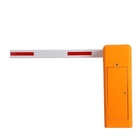
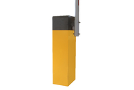
AC220 Infrared Car Park Boom Gate Automatic , DC Motor Security Barrier Gate


| Place of Origin | China |
|---|---|
| Brand Name | TS |
| Model Number | TS-ZZ011 |
| Minimum Order Quantity | 1 set |
| Price | Negotiable |
| Packaging Details | Plywood box |
| Delivery Time | 5-7 working days |
| Payment Terms | T/T, Western Union, MoneyGram, L/C, D/A, D/P |
| Supply Ability | 2000 sets per month |

Contact me for free samples and coupons.
Whatsapp:0086 18588475571
Wechat: 0086 18588475571
Skype: sales10@aixton.com
If you have any concern, we provide 24-hour online help.
xProduct Details
| Operating Voltage | 220V+10%/50HZ | Packaging Details | 24v |
|---|---|---|---|
| Operating Ambient Temperature | -40℃-70℃ | Payment Terms | T/T, Western Union, MoneyGram, D/P, D/A, L/C |
| Supply Ability | 2000 Sets Per Month | Output Power | 150W |
| High Light | AC220 Car Park Boom Gate,Infrared Car Park Boom Gate,DC Motor Security Barrier Gate |
||
Product Description
Aayee Automatic Car Boom Parking Road Traffic Barrier Car Park Barrier Gate For Parking Access Control Security Boom BarTechnical parameters
1 Working temperature(motor): -35℃~+85℃
2 Rated voltage:DC24V
3 Running speed:1.5s-8s
4 Rated current:8.58A
5 Rated power:140W
6 No-load speed:1850rpm
7 Rated speed:1400rpm
8 Output Power:56.8N.m
9 Relative humidity:≤90%
10 Remote control distance:≤100M(in the open place)
Features
1The running speed can be adjusted from 1.5s to 8s
3 Open the barrier gate by motor wheel when power off ,automatically reset after power on
4 Curved crank arm three- link movement structure, the operation is stable
5 Wireless remote control control open/close
6 Auto reverse function(force adjustable)
7 Infrared photocells connector is available
8 Loop detector connector is available.
9 Well-integrated with car parking system equipment,with wire control(must be switch signal)
10 Connector for traffic light(AC220V,power less than 40W)
11 Offering dry contact signal for car parking system(COM,NC,NO)
Arm length speed comparison table
| Menu code | Number | Menu code name | Defaults | unit | Remarks |
| H00-00 | 25-95 | Open speed adjustment | 40 | Corresponding PWM duty cycle 25%-95%, step size is 1 | |
| H00-01 | 25-95 | Close speed adjustment | 40 | Corresponding PWM duty cycle 25%-95%, step size is 1 | |
| H00-02 | 5-40 | Open in place decelerate angle | 35 | The larger the angle value, the less likely it is to shake the arm when it is in place. | |
| H00-03 | 5-40 | Close in place decelerate angle | 35 | The larger the angle value, the less likely it is to shake the arm when it is in place. | |
| H00-04 | 1-20 | Open accelerate adjustment | 10 | ms | The smaller the number, the faster the speed |
| H00-05 | 1-20 | Close accelerate adjustment | 10 | ms | The smaller the number, the faster the speed |
| H00-06 | 1-30 | Open in place angle | 2 | degree | step size is 1 |
| H00-07 | 1-30 | Open in place angle | 1 | degree | step size is 1 |
| H00-08 | 7-13 | Auto reverse force adjustment | 10 | A | step size is 1 |
| H00-09 | 0-90 | Delay closing adjustment | 0 | Sec | step size is 100;0 is not closing automatically,,Other value will be closing automatically;This parameter is for when there is no loop detector signals and non-automatic operation occasions |
| H00-10 | 10-50 | Self-check speed adjustment | 30 | Corresponding PWM duty cycle 10%-50%, step size is 1 | |
| H00-11 | 0-2 | Self-check mode | 0 | 0:no operate automatically;1:operate automatically,remove after power off;2:operate automatically,Power failure memory | |
| H00-12 | 0-5 | Self-lock force adjustment(Invalid) | 3 | ||
| H00-13 | 1-20 | Motor deceleration time when paused | 5 | The larger the setting, the longer the pause time will take | |
| H00-14 | 0-1 | The default direction of operation after self-test | 0 | 0:Closing,1:opening | |
| H00-15 | 1-10 | Number of pole pairs(Invalid) | 4 | Only used to correctly display motor speed values | |
| H00-16 | 1-32 | RS485communication address | 1 | Up to 32 slaves can be connected | |
| H00-17 | 0-2 | RS485communication rate | 0 | 0:9600,1:19200,2:38400;Change the parameter and will be valid after power on again. | |
| H00-18 | 0-1 | If self-test after power is on | 1 | 0:no self-test after power on,1:self-test after power on | |
| H00-19 | 0-3 | Manual self-test adjustment | 2 | 0:Manually invalid,1:Keyboard SET button,2:remote control valid,3,Keyboard SET button and remote control both valid | |
| H00-20 | 0-15 | Monitoring parameter setting index | 7 | 7,operation times(ms):0~9000 8,Cumulative operation times:0`99999999 9,automatically operation times :0~99999999 10,Collision times:0~99999999 11,Closing in place times:0~99999999 12,Power-on time (minutes):0~99999999 13,power-on times:0~99999999 14,Input port status:Binary display 15,Error code:0~7 |
|
| H00-21 | 0-3 | reset | 0 | 1:rest adjustment | |
| H00-22 | 0-1 | LED output mode | 0 | 0:Do not flash alternately during operation;1:Allow flashing |
Installation, commissioning and use
7.1 Equipment installation
7.1.1 Please select the correct type of barrier gate according to the specifications of
the pace,and then fix the barrier cabinet with expansion bolts(refer to Figure 3).
After determined the position,the barrier gate foundation should be done according to the site conditions,and
also make the cast-in-place basement for the non-concrete ground.
7.4 Adjust the Position of Barrier Arm
To adjust the position of the arm (for example, after exerting excessive force), please take the steps as below:
- open the barrier gate door and remove the cover
- loosen the two fasten screws of the DZ-1 on the boom shaft with the M12's Allen wrench, so that the boom can be re-positioned by hand.
- adjust the position of the boom (horizontal position, as shown in picture 1).
- Use the hexagonal wrench to tighten the two fastening screws (72 Nm)
The parameter for selecting the balance tension spring
| Arm Type | The Length of arm | Selection Spring | |
|
Type
|
Spec.(diameter*Length) | ||
| Straight Arm/Folding Arm | 6M≥L>5M | Extension Spring | (ø5.5x280)+(ø4.5x280) |
| 5M≥L≥4.5M | (ø5.5x280) | ||
| 4.5M>L≥3M | (ø4.5x280) | ||
| Fence Arm | 5M≥L≥4M | (ø6.5x280)+(ø6.5x280) | |
| 4M>L≥3M | (ø5.5x280)+(ø4.5x280) | ||
(the parameter is based on the company’s arm)
Recommended Products